Corrupted database
Due to a corrupted database with failed backups, some posts have been lost. I’ve regenerated some of the most recent ones but some are just lost forever. Le sigh.
On a positive note, my backup process has now been updated.
Rocket Workbench V5.1 released
The latest release updates the workbench with an enhanced tool for analyzing fin flutter. This implements the improvements outlined in Peak of Flight newsletter 615.
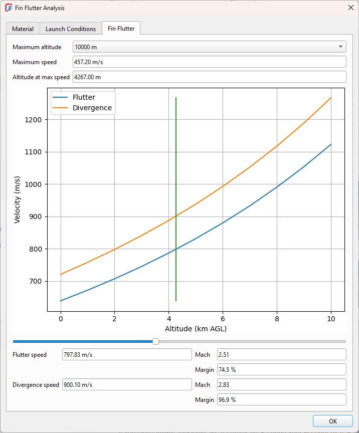
This improves the workflows as well as adding new capabilities. More fin types and shapes are supported, including triangular, elliptical, proxy, custom, and fins with varying degrees of sweep.
Rocket Workbench Scaling Workflow
If you’ve ever made a scratch built scale model, or if you’ve ever tried to create an upscale model of a classic, you know the pain of sitting down with a calculator and pad of paper to translate dimensions from the original to your desired scale. If you’ve gotten fancy you might have used a spreadsheet or other tool to do the calculations. At least the spreadsheet simplifies double checking your work.
For many designs, this is not a significant amount of effort. When I modelled my Saturn IB, it was a tremendous amount of effort. There are tools in FreeCAD that could have simplified the process, but many of those didn’t exist then. It also didn’t help that I had to use features under active development as the Part Design workbench wasn’t a released feature yet. Even now though there’s a significant amount of tedium required to do a scale model that shouldn’t be the case. Aren’t computers meant for calculating stuff?
The latest release of the Rocket Workbench introduces a workflow specifically tailored to the problem of scaling. This includes both up scaling existing designs, and down scaling for scale models. The basic workflow is simple: design your model, or import your design from your simulation tool, and apply a scale.
Let’s see how that works.
The Scaling Tab
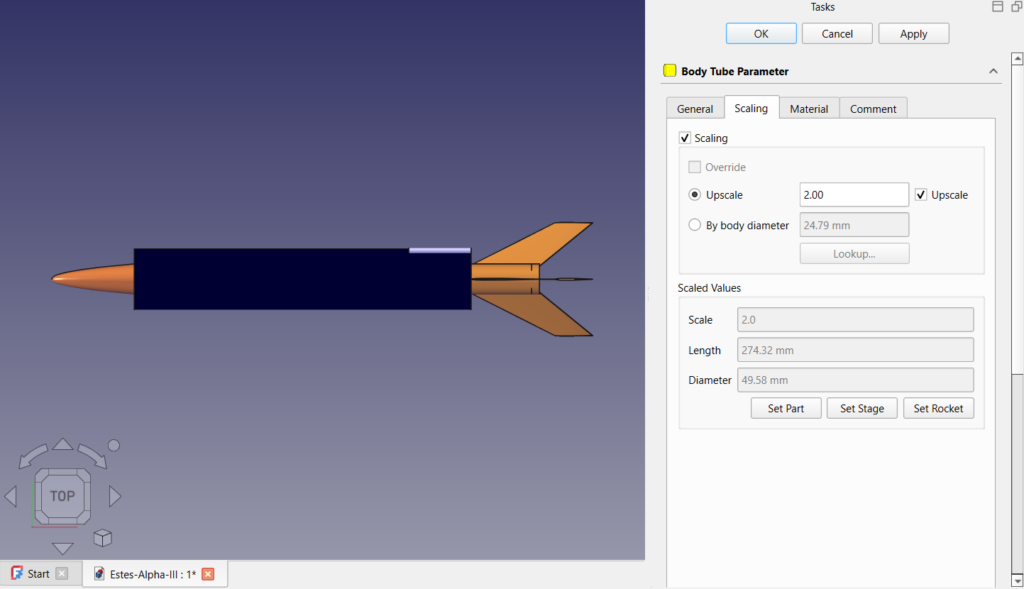
When you edit a component, it now has a scaling tab.
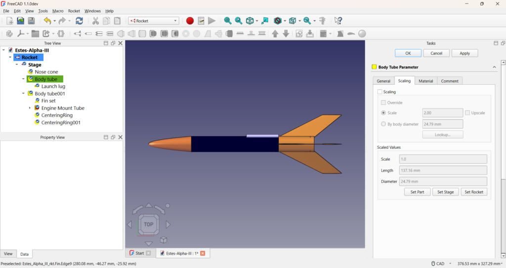
The example shown here is a model of the Estes Alpha III as imported from Rocksim. I’ve selected the body tube for editing. The tab will look different depending on the component being edited but they are all very similar.
The upper section sets the scale. If the Scaling checkbox is not selected the part will not be scaled. When scaling is selected you have options for how the part will be scaled. Scaling is conventional specified by supplying two numbers: typically it is 1:x where 1 indicates the original and the value x is used to determine the final size. For example, if you’re into HO model trains, your model train is 1:87 scale. That means if your train is 1 cm tall, your original was 87 cm tall.
Entering a value of 2 in the value field will produce a part that is 1:2 scale, or half the size of the original. This makes sense if you’re building a traditional scale model. If you’re up scaling an old favourite like the Alpha III and want to double it’s size your value needs to be 0.5, or 1:0.5 scale. That’s not very intuitive and makes you do the math instead of the computer. Instead, select the upscale checkbox and enter your value of 2.
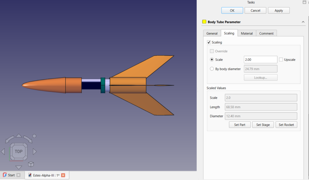
Of course, you’re still doing the math at this point. There may not be a body diameter of the appropriate size available. When you’re up scaling, you would commonly start with a specific body tube in mind. For example, let’s assume we have an LOC Precision 4″ body tube and we want to upscale to that. We would instead select “By body diameter” and specify our body diameter.
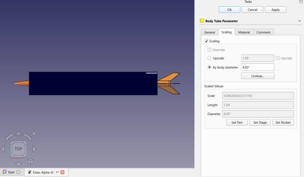
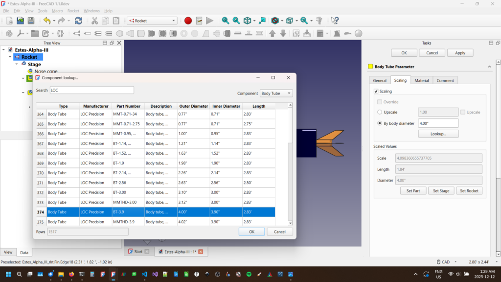
Even that is more thinking than you should have to do. You can instead use the “Lookup…” feature to select your body tube.
In the bottom of the scaling tab you see a read only section called “Scaled Values”. It shows the final scale, and the scaled value of the major external dimensions. This is important because it will not scale any internal dimensions such as thickness or inner diameter. Some of that will be set when you use the lookup feature to select a specific manufactured part but that will be important to remember later. Some inner dimensions can be set to “auto” and will automatically adjust as required. It’s important to check these to see if they are correct.
So far all we’ve done is scale one component. There’s a lot more to our rocket than a single body tube. We have options here.
Inherited Scale Values
Looking at the rocket tree on the left we see there is a hierarchy of components. Rockets have stages that have body tubes that have fins, etc. Scale values are inherited. If we set the scale of the rocket, that will apply to all components it contains. Similarly, we can set the scale for a stage, or group of components. If you want a component to be scaled differently from something higher in the rocket tree, you will need to select the override check box. Any overridden values will apply to any component in it’s sub-tree unless it explicitly overrides it.
We use this to our advantage when scaling the whole rocket instead of a single component. In the example above, we’ve selected the LOC BT-3.9 body tube for our upscaled Alpha III. We can then apply that to the whole rocket by selecting “Set Rocket”. It then scales all remaining external components to the same scale as our body tube. In this case, it adjust the dimensions of the parts and resets the scale values to 1.
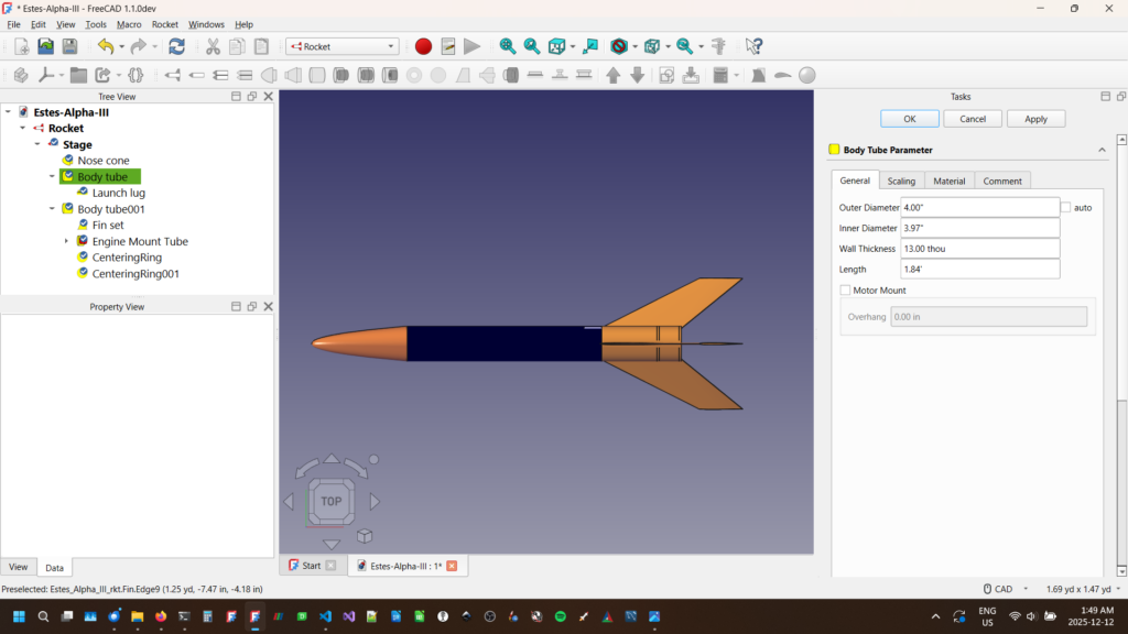
Again some caution is warranted here. Only the external components are scaled, and not all of them. Launch lugs, rail guides, and similar are not adjusted. A scaled version of a 1/8″ launch lug that was appropriate for the original Alpha III is not appropriate for a 4″ high powered version. You’ll want to use a rail button or similar. Internal components such as motor mounts and centering rings are not adjusted, although there are some auto settings that may adjust some values. An 18mm C motor is probably not going to be able to launch the larger rocket. Materials aren’t changed. Your cardboard centering ring may now need to be made of plywood. There is still work to do, but a lot of it is now simplified.
We can then export or final scale model to OpenRocket for flight simulations before building and flying.
Traditional Scale Models
This is another thing of beauty. We can design our rockets in the original dimensions of the rocket. We can then get our basic scale design by applying a scale to the rocket component and we have all of our dimensions correct. When we combine this with proxy components for more detailed features (coming in a future post), we have something very powerful indeed!
The Banshee – Musical Version
The Banshee is a fun rocket with whistles for fin pods! For a preview of the rocket and how it’s made, I’ve set a time lapse to music. Don’t forget to like and subscribe!
Nose Cones in Fusion 360
Creating nose cones in a CAD package can be challenging by hand, but easy when it’s done through software. In Part 1 of this 2 part series, I show you how to install an add in for Fusion 360 that does the work for you. Don’t forget to like and subscribe!
Get the macro: https://www.davesrocketshop.com/?page_id=67
New 3D printing blog posts
It’s been a busy time with the 3D printer. In addition to some heavy duty runs printing Saturn V parts, I’ve solved issues on 2 different fronts, resulting in not one but two different blog entries! Check them out here: https://www.davesrocketshop.com/?page_id=148
New Patreon Subscribers FIle Access Page
Select Patreon subscribers get access to files a full 4 weeks before they’re released to the public.
The member page is publicly accessible here, but you’ll need a password to access the files. This password will change monthly and be made available to current Patreon subscribers. Thanks for your support!
Patreon Launch – with a limited time special give away!
I’m officially announcing my new Patreon channel. As part of the introduction all members will be given a specially designed rocket just for patrons! This is a limited time special so please sign up soon!
My design files will be posted for sponsors a month before the general public, as well as some limited edition designs just for subscribers.
Saturn V Part 4 Transitions, S IVB, and Scale Issues
The stack is progressing! In this issue I talk about the S-IVB stage and its transition to the lower airframe. More importantly I talk about an issue with the scale for the flyable version. Don’t forget to like and subscribe!
Saturn V Part 3 Printing the SLA
Below the CSM comes the SLA (Service Module to Lunar Module Adapter). In this video I discuss some basic printing tricks that can significantly reduce the amount of plastic used and time required to print. Don’t forget to like and subscribe!