The latest release updates the workbench with an enhanced tool for analyzing fin flutter. This implements the improvements outlined in Peak of Flight newsletter 615.
This improves the workflows as well as adding new capabilities. More fin types and shapes are supported, including triangular, elliptical, proxy, custom, and fins with varying degrees of sweep.
Fin flutter describes a harmonic vibration that can be introduced due to aerodynamic forces. It can build over time until seemingly rigid materials “flutter” as if the fin were made of thin paper. In extreme cases it can cause catastrophic failure of the fin. Searching for “fin flutter rocket” on YouTube can yield some fascinating videos. Preventing this is a key concern to builders and flyers of high power rockets. The FreeCAD Rocketry Workbench introduced a fin flutter analyzer quite some time ago.
The original Fin Flutter analysis dialog implemented the method of approximating fin flutter as described in Peak of Flight newsletter 291 (POF291), which in turn implemented the method described in the NACA Technical Note 4197. Both were useful, but both had errors and limitations.
The original NACA paper was written by engineers who were quite happy using constants without specifying the units in an archaic measurement system. To be fair the paper is fairly old having been published in 1958. Luckily FreeCAD can support this archaic system of measurements while using metric units internally. The lack of units for constants is unfortunately a common engineering practice which frustrates the scientist in me. Without adequate explanation, these constants had to be adjusted through reverse engineering. The paper also hints at handling swept fins without a full explanation. I meant to revisit this after the initial implementation, but it was one on a long list of features that never received the attention it deserved.
The Peak of Flight article had a very good description of the problem and its implementation. It was limited to trapezoidal fins of consistent thickness and a limited atmospheric model. This was improved slightly in Peak of Flight newsletter 411 (POF411) which also simplified the formulas for an SI implementation. Both of these however had an error that overestimated fin flutter by a factor of 1.414 (square root of 2) and were limited to trapezoidal fins.
Enter John K. Bennet and Peak of Flight newsletter 615 (POF615) and Peak of Flight newsletter 617 (POF617). In these two articles, John digs deeper into the formulas to describe a method of calculation that fixes the overestimation while incorporating a variety of fin shapes. He does all of the math that I was too lazy to do before, with a great explanation of what he is doing. Additionally, he provides values for the Shear modulus for a number of commonly used fin materials. This prompted a revisit of the Rocketry Workbench Fin Flutter Calculator dialog.
Units
FreeCAD works with a variety of unit systems. Your preferred units can be set in the preferences. Dimensions can also be set in any of the dimensioned input fields by specifying the units. For example, an altitude can be set as “14000 ft” or “4276.2 m”. It will then be converted to your preferred units for display. Internally, all dimensions are in mm but that’s transparent to the user.
Alternatively you can change your preferred units for the current session. Selecting the dimensions in the bottom right corner brings up a menu that will allow you to select the units for your session.
I will be using both metric and imperial units throughout this article.
Materials
The Rocketry Workbench already had a large list of supported materials, but the physical properties of those materials were minimal. These have been updated to include the Shear modulus values given in POF615. While these are only approximate, they will give good results within an acceptable margin of error in most cases. Truly accurate results would require measurements taken from the actual materials being used especially for materials such as wood that have a high degree of variability. The results should be evaluated with a significant safety margin to allow for this variability. In his article, Mr. Bennet recommends a safety margin of at least 25%, with a margin of less than 20% considered unsafe.
The good news is that these materials are automatically populated when importing your OpenRocket or Rocksim design files.
Complex Fin Shapes
POF617 describes the handling of complex fin shapes. This is fairly easy to implement in FreeCAD subject to other CAD based limitations.
In particular, the calculation of the axial distance from the front of the fin to the fin centroid, or center of mass (referred to as Cx in the article) is extremely easy. Each shape in FreeCAD has a property called CenterOfGravity with components in the x, y, and z dimensions. It’s already calculated for you by the core libraries. Other useful properties are Volume and Area. Care is needed when using the Area property as it’s a surface area and not the area projected on to a plane. For sketch-based fins though the area of the face produced by the sketch is the equivalent of the fin’s projection onto the X-Z plane.
Without getting too deep into details, there are limitations for a CAD based implementation. For example, handling airfoiled fins with a sketch-based design make the bat style fin used in his article challenging to handle in a generic way. The solution is to use the Rocket Workbench’s proxy feature to draw the fin using the Part Design workbench instead. Some equivalences for specific parameters such as root chord need to be provided to use the fin with the flutter calculator. This will be the subject of a future article. Meanwhile the model is shared in the case study later in this article.
Atmospheric Models
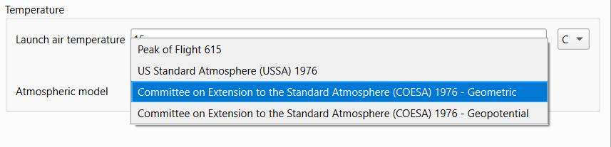
The various articles mentioned all include a simple atmospheric model. All are useful with specific limitations such as altitude. For example, the model described in POF615 is valid up to about 12 km or 37000 feet. For the vast majority of model rockets that is more than sufficient. The dialog implements other models for other conditions. The United States Standard Atmosphere (USSA) 1976 standard provides a model suitable for use up to approximately 84 km. The Committee on Extension to the Standard Atmosphere (COESA) 1976 standard extends this up to 1000 km. These models take into account the varying composition and density of air gases with altitude. Additionally, they offer the geometric variant which factors in the actual measured altitude, and the geopotential variant which factors in gravitational variances to produce an equivalent altitude typically smaller than the geometric altitude. The differences between the models are slight. They should be significantly less than your safety margins.
For most purposes, all models will produce acceptable results. If you’re validating against known calculations, you’ll need to select the same atmospheric model.
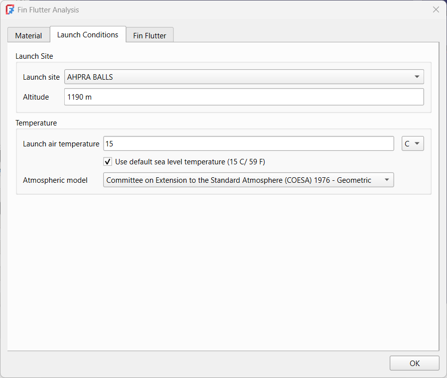
Launch Conditions
There are a number of factors that can affect fin flutter primarily atmospheric. Many such as humidity are not factored in because the most relevant value is the humidity at altitude, not at the launch site. The altitude of the launch site is important when converting from Above Ground Level (AGL) to Above Sea Level (ASL) values as the ASL value is used for atmospheric calculations while most flyers are thinking AGL. For convenience, a number of launch sites are included in a combobox to set the launch site altitude, or it can be set manually. This list is taken from the Altus Metrum launch site list with values added for the altitude.
You have the option of using the standard sea level temperature of 15 C or adjusting to the temperature at your launch site.
Finding Fin Flutter
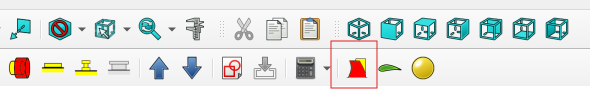
Finding fin flutter starts with a fin. It can be the fin on its own, or the fin from the model of a complete rocket. We’ll be using both in our case studies. From your FreeCAD design file, select the fin. You will then be given the option to run the analysis from the toolbar.
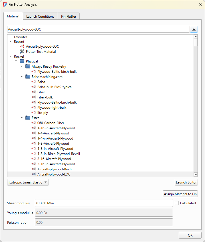
The dialog starts you in the Material tab. Ensure your material is correct and that you have a value for Shear modulus. Next progress to the Launch Conditions tab and ensure all settings are as desired.
Finally finding fin flutter is simply a matter of setting the “Altitude at max speed” value, or any altitude at which you desire a flutter value. The altitude can also be set by adjusting the slider at the base of the graph. The “Maximum speed” value is used to calculate the safety margins.
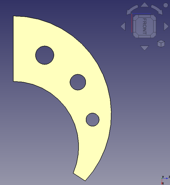
Case Study: Trapezoidal Fin
This example is taken directly from POF615. It is used as a validation test case.
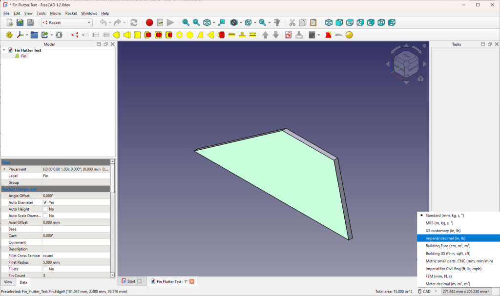
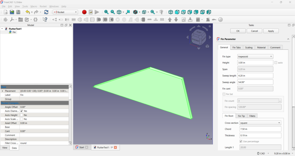
The fin was created manually using the Rocket Workbench’s fin tool. The nice thing about FreeCAD is that even though all dimensions are metric internally, the user can specify their preferred units. Since the document describes the dimensions in inches, we use the same here.
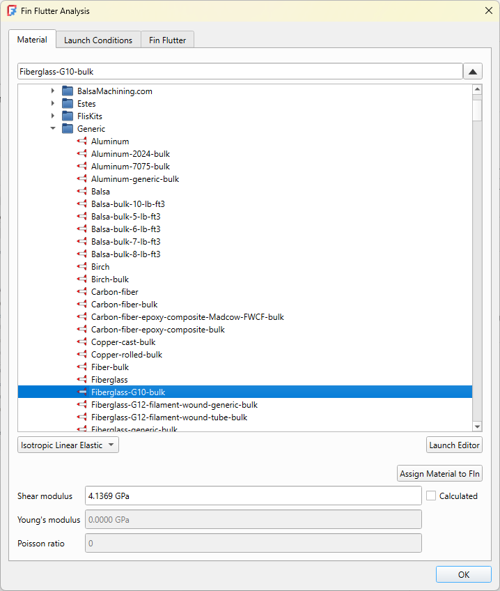
Selecting the fin, we then get the option to run the flutter analysis dialog. You are initially presented with the material selector. The example in the article is made of fibreglass, so we will select the generic fibreglass material. We can assign this material to our fin by clicking on the button. This means it will be set if we ever have to rerun our analysis.
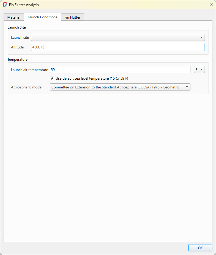
We then move on to the Launch conditions dialog. Most of the default values are fine, but we’ll set the launch site altitude to 4500 ft as in the article.
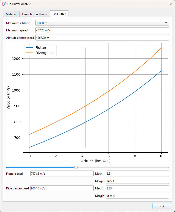
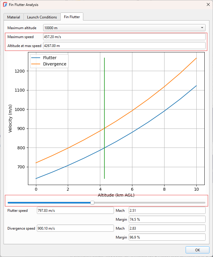
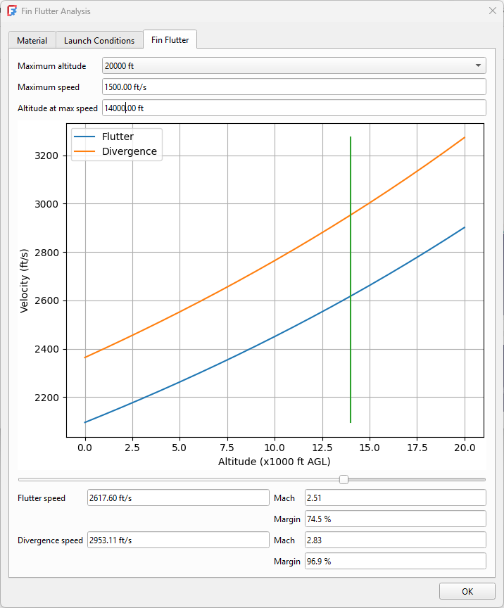
Finally, we’ll set the parameters for the fin flutter calculations. Here we need to set the altitude at max speed to 14000 ft (AGL). The speed isn’t necessary for the flutter calculations but setting its value will allow us to calculate the error margins. The speed in this case is 1500 ft/s.
We can see that for this example, our error margins are well within the acceptable range.
Case Study: Bat Fin
The POF617 newsletter used a bat fin as an example of an unusual fin shape. It’s not an easy model for the Rocket Workbench, but it is very simple for the FreeCAD Part Design workbench. Integrating that with the Rocket Workbench is a matter of using the fin proxy feature. I will be writing more about that in an upcoming article. In the meantime, here is the FreeCAD design file.
The article describes a series of steps required to calculate the center of mass for such an odd shape, but as I previously mentioned FreeCAD already calculates that for me with no extra operations required.
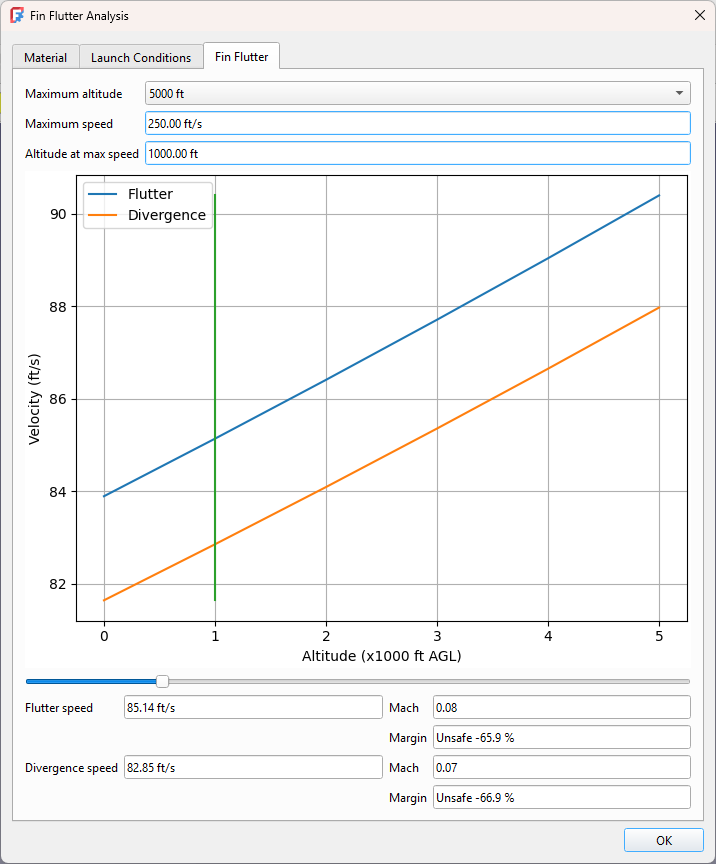
The article then describes testing the fin with a variety of materials and thicknesses. Starting with 1/16″ balsa, we can see that flutter is definitely expected to be a problem.
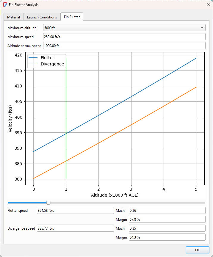
Experimenting with a variety of materials and thicknesses, we finally settle on 1/8″ birch plywood.
As we can see, integrating this tool into our design process can greatly increase our chances of a successful flight even for a rocket going subsonic to 1000 ft.
Case Study: Apogee Perigrine
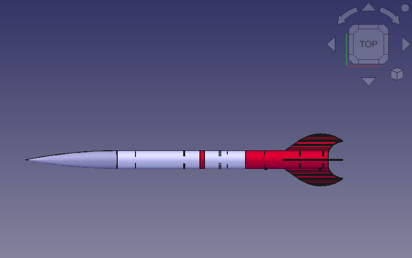
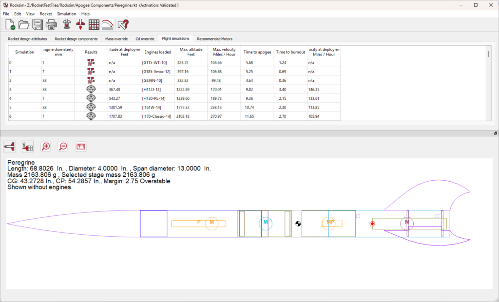
The Apogee Perigrine is a commercial rocket design by Apogee Components, who also make the Rocksim design and simulation tool. It is a classic example of unusual fin shape. It was also featured on the cover of POF617 even though it wasn’t mentioned in the article.
Having the Rocksim design file simplifies our work quite a bit. Instead of designing the fin, we can just import the file directly into FreeCAD. We can see from the flight simulations tab in the image above we also have a few motor configurations to test.
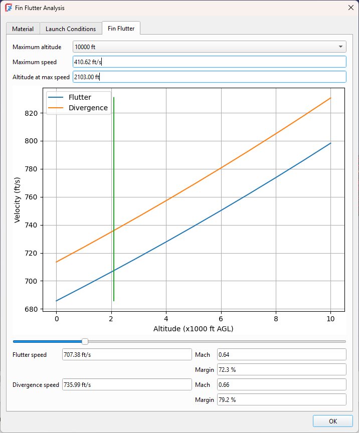
The Rocksim tool doesn’t report the altitude at maximum velocity, but it does tell us the maximum altitude so we can start from there. It also doesn’t tell us the maximum speed in ft/s, but as I mentioned at the start of the article FreeCAD works with a variety of units so we can enter the speed in mph.
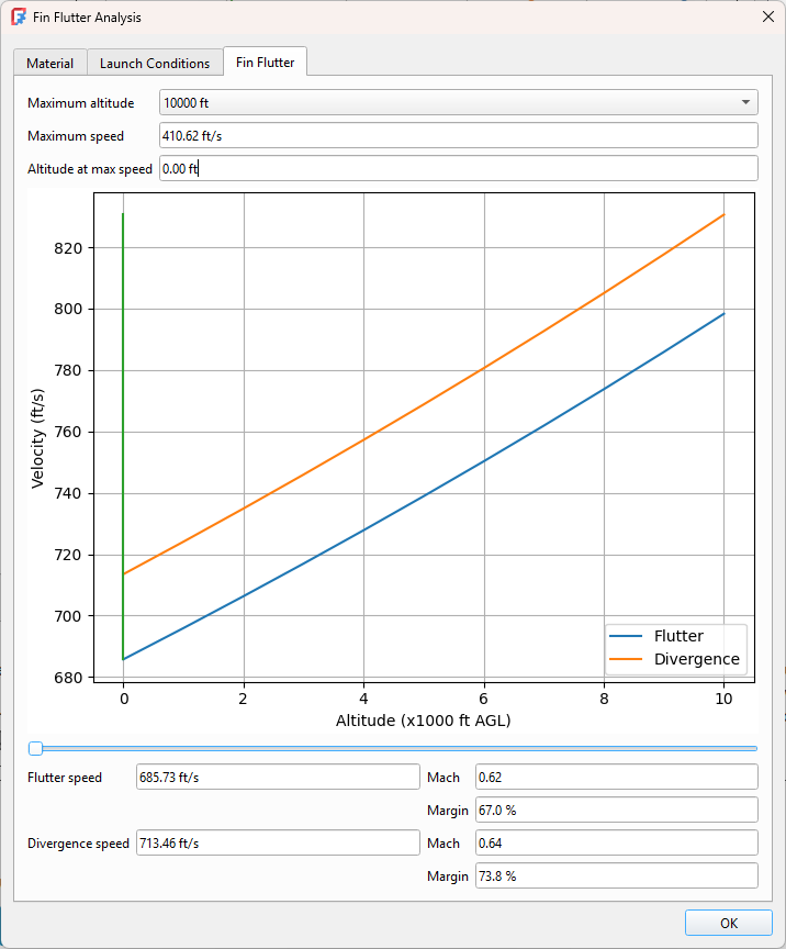
We can see we have a good safety margin at maximum altitude, but this is not where we achieve maximum speed. We could go to the simulation graphs to determine where the maximum speed was achieved, but an easier way is to use the slider to adjust the altitude and examine the results over the entire range. Even setting the altitude to 0 where the flutter speed is the lowest shows we have significant safety margin. This rocket is ready to fly!
Future Work
I’ve taken great pains to ensure the results produced agree with known results, or at least with results as published. Complex fin shapes in particular have not been sufficiently validated. The original NACA paper described non-swept trapezoidal fins, whereas the techniques shown here extrapolate that to a large variety of fin shapes. Ideally this would be validated against wind tunnel measurements. If you have any suitable test cases I’d love to see them.
In the absence of a wind tunnel there are numerous computational techniques that model fin flutter. This includes both CFD and FEM analysis, with better methods incorporating both. That is a long-term goal for the Rocket Workbench. Both types of simulation are already supported by FreeCAD.
Conclusion
Fin flutter is a complex topic. Analysis requires a number of simplifying assumptions. Like all modeling it is possible to get confident but incorrect results.
Always, always, always ensure you have a sufficient error margin to allow for errors in input.